What Are the 7 Best Steel Fabrication Process Steps?
Steel fabrication turns raw metal into reliable structures, machine parts, frames, and support systems. The steel fabrication process demands more than cutting and welding. It requires accurate drawings, suitable materials, controlled heat, skilled technicians, and careful inspection. A small measurement error can shift a beam several millimeters, affecting the entire assembly.
This guide explains seven essential steel fabrication process steps, from planning and material selection to finishing and final quality checks. Each stage has a practical purpose. Design review helps identify unclear dimensions. Material preparation creates clean, workable surfaces. Cutting and forming give steel its required shape. Welding joins components under controlled conditions. Grinding, drilling, and surface treatment improve fit and durability. Inspection then verifies dimensions, weld quality, and coating coverage.
Real fabrication work is rarely perfectly smooth. Material thickness may vary slightly. A drawing may need clarification. Heat can create distortion, even with experienced welders. These details matter. They show why experienced judgment supports written procedures and inspection records. Industry standards, qualified personnel, calibrated tools, and traceable documentation strengthen each project.
Some workshops move quickly. That is not always better. Rushed fabrication can leave sharp edges, weak joints, or hidden alignment problems. Good results come from balancing production speed with safety and precision. The following seven steps provide a practical framework, while recognizing that project specifications, steel grades, and applicable standards may change the exact process.
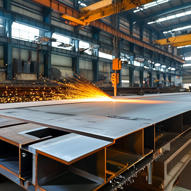
Steel Fabrication Planning, Design, and Material Selection
What Are the 7 Best Steel Fabrication Process Steps?
Steel Fabrication Planning, Design, and Material Selection
Effective steel fabrication begins with a clear project brief, site measurements, and realistic load requirements. The process then moves through seven practical steps: planning, design, material selection, cutting, forming, welding, and inspection. Experienced fabricators check access routes before approving drawings. A steel beam that fits the workshop may not fit through a narrow doorway.
Design should show dimensions, weld symbols, connection details, and acceptable tolerances. Engineers also review corrosion exposure, expected loads, and installation conditions. Material selection must match performance needs, not just price. Check grade certificates, thickness, surface condition, and availability before cutting begins. Mild steel may suit an indoor frame, while a coated or corrosion-resistant option may perform better outdoors. A perfect plan rarely survives the site unchanged. Revisions are normal, but unclear revisions create expensive errors.
Tips:
Keep one controlled drawing set. Mark every revision clearly. Measure twice before cutting. Leave practical access for welders and inspection tools. Store steel above damp floors, and protect finished edges from impact. Cutting lists should include kerf allowances and nesting efficiency. Inspect fit-up before welding, because small gaps can become visible distortion. Record weld inspections, dimensional checks, and material documents. Digital records help, but they still need human review. A missed detail on paper can become a misaligned frame in the workshop.
Steel Cutting and Component Preparation
Steel Cutting and Component Preparation
In the seven best steel fabrication process steps, cutting controls the quality of every later operation. Skilled fabricators begin by checking the drawing, steel grade, thickness, and required tolerances. A small mistake here can affect welding, drilling, and final alignment. Measurements should be confirmed with calibrated tapes, gauges, or digital tools. Material heat numbers also need clear tracking for reliable inspection records.
The cutting method depends on thickness, shape, and edge requirements. Laser cutting can produce clean profiles, while plasma suits many medium-thickness sections. Oxyfuel cutting remains useful for heavier plate when heat control is carefully managed. Operators should consider kerf width, heat-affected zones, and distortion before cutting. The programmed line is not always the finished edge. Allowances may be needed for grinding or later machining. After cutting, workers remove dross, sharp burrs, and loose scale. Holes and notches should be checked against the drawing, not guessed from appearance. An experienced inspector examines edge quality under good lighting and measures critical dimensions again. Even careful teams make errors. A slightly shifted cut may look acceptable until assembly exposes the gap. Dry fitting components can reveal this problem early. Component labels, orientation marks, and protected edges then keep preparation organized on the shop floor.
Forming, Drilling, and Edge Processing
A reliable steel fabrication route usually has seven steps: drawing review, material preparation, cutting, forming, drilling, edge processing, and inspection. The middle operations deserve special attention. Global crude steel production reached about 1.89 billion tonnes in 2023, according to World Steel Association data. At that scale, small process errors can create significant waste.
Forming starts with the correct bend allowance, tooling radius, and grain direction. Operators should record actual springback, not rely only on software values. Measure twice. Heat changes everything. Excessive forming pressure may produce cracks, local thinning, or hidden distortion. After forming, drilling should follow a controlled sequence. Center-punching prevents wandering, while pilot holes improve accuracy on thick plate. Coolant, suitable feed rates, and regular tool inspection also reduce burrs and overheating. The International Energy Agency reports that iron and steel production creates roughly 2.6 gigatonnes of carbon dioxide emissions annually, so avoiding rejected parts has both financial and environmental value.
Edge processing is often treated as a minor finishing task, but sharp edges can damage coatings, cables, and workers’ gloves. Deburring, chamfering, or grinding should match the drawing and the final assembly requirement. Inspect hole diameter, edge condition, bend angle, and flatness with calibrated tools. ISO tolerances are useful, yet they cannot replace practical judgment on distorted parts. A weakness in many workshops is inconsistent inspection records. One perfect sample proves little. Batch traceability, photographs, and dimensional logs provide stronger evidence. Some parts still need rework, and that should be studied rather than hidden.
Component Assembly, Welding, and Structural Joining
The seven best steel fabrication steps are practical controls, not a rigid ritual. They include drawing review, material verification, cutting, forming, fit-up, component assembly, and final joining. For structural work, the last three demand the most judgment. A two-millimeter gap can change weld penetration, distortion, and field alignment. It looks minor. It isn’t.
The World Steel Association’s 2024 statistical report recorded about 1.89 billion tonnes of crude steel production in 2023. That scale makes repeatable fabrication essential. During component assembly, fabricators check orientation, datum points, temporary restraints, and bolt-hole alignment before welding. Qualified procedures should define joint geometry, consumables, preheat, heat input, and inspection points. Welding then follows a controlled sequence, using balanced passes to limit shrinkage. Structural joining may combine welds, high-strength bolts, or both. Each connection needs traceable records, not confident guesses.
Industry safety guidance treats inspection as part of production, not a final rescue step. Visual inspection can catch undercut, overlap, arc strikes, and incomplete weld profiles early. Ultrasonic or radiographic testing may be selected when risk and specifications require it. The International Energy Agency estimates steelmaking creates roughly 7–9% of global energy-related emissions, so avoidable rework matters. Yet perfect workflow claims deserve skepticism. Moisture, warped plate, and rushed delivery can defeat a good procedure. Experienced teams pause, measure again, and document deviations before continuing.
Surface Treatment, Inspection, and Final Quality Control
Steel fabrication does not end when the weld bead looks smooth. Surface treatment and inspection determine whether the finished part survives real service. After cutting, forming, welding, and grinding, technicians remove slag, spatter, oil, and sharp edges. A clean surface reveals defects that paint might hide. It also improves coating adhesion. Small details matter.
In my experience, abrasive blasting or mechanical cleaning should match the project specification and steel condition. Technicians check surface profile, temperature, humidity, and dust before applying primer or protective coating. A rushed wipe can leave oil around a weld toe. That mistake is easy to miss. It may cause early peeling under moisture and load. Coating thickness requires several readings, especially near corners, edges, and recessed areas.
Inspection continues through final quality control. Calibrated tools verify dimensions, hole positions, flatness, and assembly alignment. Visual weld checks identify cracks, undercut, porosity, and incomplete cleaning. When required, non-destructive testing provides deeper evidence without damaging the component. Inspectors record results, repair locations, and reinspection status. A perfect report cannot correct a poor inspection. That remains a practical weakness in busy workshops. Final approval should include drawings, material records, coating data, photographs, and signed inspection results. One overlooked corner can still decide the service life of the entire structure.