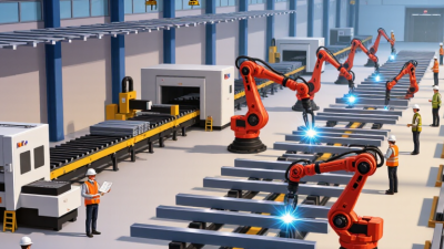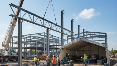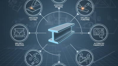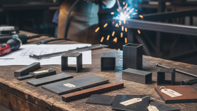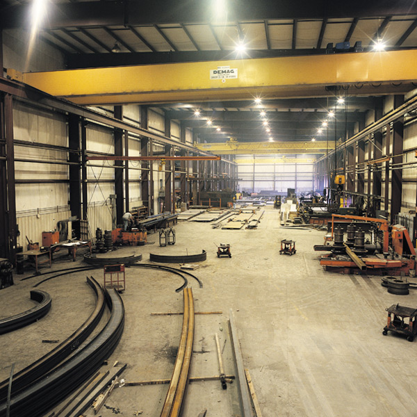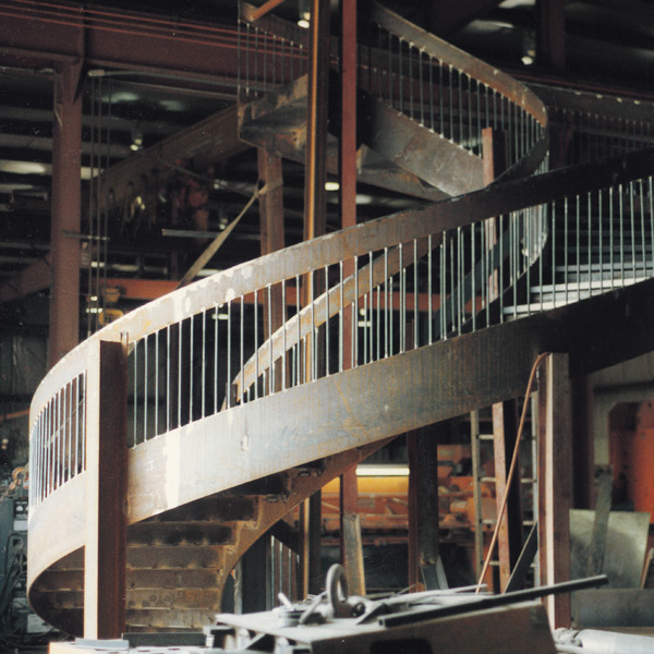

A steel staircase starts as plate, sections, and a drawing with dimensions someone must interpret correctly. Steel fabrication turns those materials into usable structures through cutting, forming, fitting, welding, and assembly. Precision matters. A misplaced hole can prevent a connection from fitting, even when every individual component looks acceptable. Understanding steel and fabrication means looking beyond sparks to the decisions that determine fit, strength, and service life.
Steel industrialist Andrew Carnegie famously advised, “Watch the costs and the profits will take care of themselves.” His words highlight an enduring manufacturing concern: wasted material and avoidable rework consume money. Yet cost alone cannot define good fabrication. A workshop might use a laser to cut thin plate and a press brake to form brackets. Fabricators then position components, check dimensions, and weld according to the applicable drawings and procedures. Checks continue throughout. Material identification, weld inspection, and coating preparation help establish whether the finished assembly meets specified requirements. Depending on the application, inspectors may also examine welds using ultrasonic or magnetic particle testing.
The process sounds orderly on paper, but workshop conditions introduce complications. Heat can distort an assembly. Drawings sometimes leave questions unanswered, and an apparently minor revision can change how parts fit together. Mistakes still happen. Calling fabrication simply “cutting and welding” is convenient, but that description overlooks planning, inspection, and practical judgment. This introduction cannot establish which process suits every project; material grade, loading, tolerances, and exposure conditions all matter. Understanding those choices makes the journey from raw steel to finished component easier to evaluate.
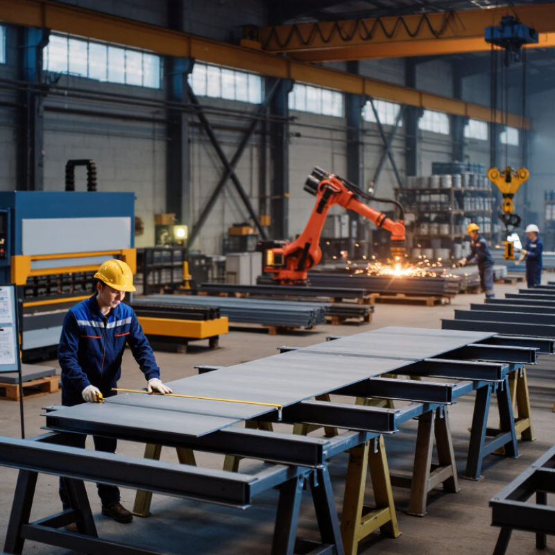
Steel fabrication turns steel stock into parts and assemblies for structures, equipment, and everyday products. A fabricator might cut a plate, drill bolt holes, and weld stiffeners onto it to create a supporting bracket. Steelmaking is different: it produces steel from iron-based raw materials or recycled scrap, controlling chemistry before casting. Rolling mills then shape that steel into products such as plates, beams, and bars, which fabricators purchase for specific jobs. The distinction matters. Fabrication changes dimensions, geometry, and connections; steelmaking establishes the material’s composition and many of its underlying properties.
Fabrication usually starts with drawings that specify dimensions, steel grades, connection details, and acceptable tolerances. Workers or automated machines cut the stock using saws, lasers, or plasma equipment, depending on thickness and accuracy requirements. Press brakes bend plate, while fixtures hold components in position during assembly. Heat changes things. Welding can pull a component out of alignment, so weld sequence and restraint deserve attention. Even a neatly finished weld may contain defects that require inspection beyond a visual check.
Material selection connects the two processes, because fabrication cannot reliably compensate for steel with unsuitable strength, toughness, or weldability. Material certificates help confirm the supplied grade and relevant test results. Inspectors may check hole locations, assembly dimensions, and weld quality against the specified requirements. Some work still needs correction: a misplaced hole or distorted flange can mean rework, added cost, or replacement. A practical drawing should leave room for manufacturing tolerances without weakening the intended connection.
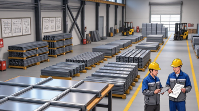
Steel fabrication turns steel sections and plates into components through cutting, drilling, forming, welding, and assembly. Drawings guide that work. The 2024 World Steel in Figures report records global crude steel production of 1,892 million tonnes in 2023. At workshop scale, production depends on precise instructions for each individual component. Fabrication drawings specify dimensions, hole locations, weld symbols, material grades, and piece identification marks. A beam connection detail might show four bolt holes, their spacing, and the required edge distances.
Grade selection matters. Under ASTM A36/A36M, common structural plate has a specified minimum yield strength of 250 MPa, subject to thickness provisions. ASTM A572/A572M Grade 50 specifies 345 MPa minimum yield strength within its applicable product limits. These values guide engineering calculations; they do not automatically make two grades interchangeable. Welding procedures, toughness requirements, thickness, and service conditions also affect suitability. Before cutting, workers should match the drawing’s grade designation against material certificates and traceable identification.
Revisions need attention. A revised hole pattern can leave an accurately cut plate unusable for its intended connection. Drawing revision checks therefore belong before machine programming and material release. Yet a drawing can look complete while leaving insufficient space for a welding torch. That deserves another look. A useful fabrication review checks tool access, weld sequencing, and inspection access alongside dimensions. Clear drawings reduce uncertainty, but they still need practical scrutiny from the people making the parts.
Steel fabrication turns plates, bars, and sections into components by cutting, drilling, forming, and joining them. Work usually starts with drawings that specify dimensions, hole positions, material grades, and acceptable tolerances. Thickness matters. A bandsaw can cut structural sections, while laser or plasma equipment follows programmed profiles in plate. For a bracket cut from 6 mm plate, the operator must account for material removed by the cutting process. Sharp edges and attached slag need removal before handling or further processing.
Drilling creates holes for bolts, pins, or other connections. A drill press or CNC machine positions the tool, while clamps prevent the steel from shifting. Cutting fluid helps control heat and tool wear, although the appropriate product depends on the operation. When a hole sits close to a bend, its location deserves attention because forming can distort the surrounding material. A hole can look correct and still cause assembly trouble if its position falls outside the drawing tolerance. Visual checks alone are imperfect.
Shaping changes flat or straight stock into the required geometry. A press brake forms bends, while rollers produce curves in plate or sections. Check the springback. Steel partly rebounds after bending, so tooling and bend settings must account for its grade and thickness. Trial bends help establish settings, but variations between material batches can still require adjustments during production. Inspectors then check dimensions, bend angles, and hole spacing against the drawing before components move to assembly.
Steel fabrication converts steel plate, sheet, bar, tube, and structural sections into components through cutting, hole-making, forming, joining, and finishing.
| Process | How It Works | Typical Applications | Key Capabilities | Limitations and Quality Checks |
|---|---|---|---|---|
| Saw Cutting | A toothed blade removes material as chips to divide steel stock into specified lengths. | Cutting bars, tubes, beams, and other structural sections to length. | Produces straight or angled cuts without the heat-affected zone associated with thermal cutting. | Blade selection and cutting conditions depend on the material and section size. Check length, cut squareness, and burrs. |
| Laser Cutting | A focused laser heats the steel while an assist gas helps remove material from the cut. | Sheet and plate components with detailed profiles, slots, and holes. | Produces a narrow kerf and can cut complex shapes under computer numerical control (CNC). | Thickness capacity and edge quality depend on the equipment, steel grade, and settings. Check dimensions, dross, and the heat-affected zone. |
| Plasma Cutting | A constricted electric arc creates a high-temperature plasma jet that melts and ejects electrically conductive metal. | Steel plate profiles, brackets, base plates, and structural fabrication parts. | Cuts carbon steel and stainless steel; commonly used for medium and thick plate. | Edge bevel, dross, and a heat-affected zone can occur. Check profile dimensions and edge condition before assembly. |
| Oxy-Fuel Cutting | A fuel-gas flame preheats steel, and an oxygen jet oxidizes the metal and removes the resulting oxides. | Thick carbon steel plate, heavy structural parts, and weld preparation. | Well suited to thick carbon steel and can be used with portable or mechanized equipment. | Conventional oxy-fuel cutting is generally unsuitable for stainless steel. Check slag, edge quality, and thermal distortion. |
| Abrasive Waterjet Cutting | A high-pressure water stream carrying abrasive particles erodes the steel along a programmed path. | Heat-sensitive parts, steel plate profiles, and components requiring limited thermal effects. | Does not create a heat-affected zone from the cutting process and works with a wide range of steel grades. | Cutting speed typically decreases as thickness increases. Check taper, surface striations, and dimensional accuracy. |
| Drilling | A rotating drill removes material to create a round hole; additional operations can refine its size or finish. | Bolt holes, mounting holes, and holes that will later be tapped or reamed. | Produces holes in plate, sections, and machined parts using manual or CNC equipment. | Check hole diameter, location, perpendicularity, and exit burrs. Cutting speed, feed, and lubrication affect tool life and hole quality. |
| Punching | A punch forces steel into a die opening, shearing out a hole or shaped feature. | Repeated holes and slots in sheet, plate, and selected structural sections. | Produces repeated features quickly when the material thickness and equipment capacity are suitable. | Punching force rises with material strength, thickness, and cut perimeter. Check burrs, distortion, and hole-edge condition. |
| Press Brake Bending | A punch presses steel into a die to form a bend through plastic deformation. | Brackets, channels, enclosures, trays, and folded plate components. | Creates controlled bend angles and flanges from flat sheet or plate. | Springback affects the final angle. Check bend angle, flange dimensions, inside radius, and cracking; account for steel grade and rolling direction. |
| Roll Forming and Plate Rolling | Roll forming progressively shapes strip through successive roll stands; plate rolling curves sheet or plate between rolls. | Long profiles, curved panels, cylinders, cones, and tank shells. | Roll forming supports repeated profiles, while plate rolling produces large curved components. | Check profile dimensions or curvature, springback, and surface condition. Minimum radii depend on material properties and machine capacity. |
| Welding | Common arc-welding processes use an electric arc to melt and join steel, often with filler metal. | Frames, assemblies, stiffeners, built-up sections, and fabricated vessels. | Joins individual fabricated pieces into larger, permanent assemblies. | Heat input can cause distortion and alter local material properties. Check weld size and appearance; use additional inspection as required by the specification. |
| Machining | Cutting tools remove material through operations such as milling, turning, boring, and reaming. | Precision mating surfaces, bearing seats, accurate bores, and threaded features. | Refines geometry and surface finish where fabrication alone does not meet the specified requirements. | Check dimensions, geometric tolerances, and surface finish. Workholding, tool wear, and residual stress can affect accuracy. |
| Surface Preparation and Finishing | Cleaning, abrasive blasting, grinding, and selected coating processes prepare or protect the component surface. | Painted structures, galvanized components, and parts requiring smooth edges or a specified appearance. | Removes contaminants or surface irregularities and supports corrosion protection when an appropriate coating system is applied. | Check cleanliness, surface profile, edge condition, and coating thickness where applicable. Select the finish for the steel grade and service environment. |
Process selection: A component may use several of these methods, and the sequence varies with its design. Achievable tolerances, thickness limits, bend radii, and production rates depend on the steel grade, geometry, equipment, tooling, and project specification.
Steel fabrication turns steel plates and sections into components that fit together as a working structure. Assembly brings those pieces into position using fabrication drawings, reference marks, clamps, and temporary supports. A fabricator checks hole locations, connection angles, and overall dimensions before securing the joints. Fit matters. A small alignment error at one connection can leave a beam sitting incorrectly at the next.
Welding joins steel by melting the joint edges, usually with added filler metal. Before welding, workers remove contaminants and prepare the joint edges to the specified shape. Small tack welds hold the pieces while alignment is checked again. Heat causes movement. An uneven welding sequence can pull a plate out of square, even when the original setup looked correct. A qualified welding procedure defines requirements such as consumables, preheat, and welding parameters. Visual inspection checks weld size and visible defects; specified joints may also require ultrasonic or magnetic particle testing.
Bolted connections secure components through aligned holes, often allowing convenient assembly at the construction site. Workers bring the connected surfaces into proper contact before completing the specified tightening procedure. Some joints require pretensioned bolts; others use snug-tight installation, depending on the connection design. An ordinary wrench check cannot verify every pretensioning method. If holes fail to align, forcing bolts through can conceal a fabrication or positioning problem. The team should check dimensions and obtain an approved correction before altering the connection.
Steel fabrication turns steel sections and plates into components through cutting, drilling, forming, and welding. Before finished steelwork leaves the workshop, inspectors compare dimensions, hole positions, and weld locations against approved drawings. A misplaced bolt hole can delay installation, even when the surrounding welds look sound. Details matter. Visual checks look for cracks, undercut, distortion, and sharp edges that could weaken connections or compromise protective coatings. Where specified, ultrasonic or magnetic particle testing helps identify defects that visual inspection alone may miss.
Corrosion protection starts with surface preparation, not paint. Fabricators remove oil, rust, and mill scale using methods suited to the specified coating system. Abrasive blasting creates a surface profile that helps coatings adhere. Inspectors check surface cleanliness, profile depth, and environmental conditions before application. Moisture can interfere. Steel temperature must meet the coating specification’s required margin above the dew point. Dry film thickness gauges then help verify that the applied coating meets specified requirements.
Weld toes, edges, and bolt recesses deserve particular attention because coatings can become thin or uneven there. Stripe coats provide extra coverage in these vulnerable areas when required by the specification. Hot-dip galvanizing offers another protection method, although hollow sections need suitable venting and drainage provisions. No finish is flawless forever. Handling damage, inaccessible corners, and trapped water remain practical concerns. Inspection records should document measurements, repairs, and acceptance criteria, while maintenance plans should reflect actual exposure conditions.
Steel fabrication turns steel sections and plates into finished components through cutting, forming, welding, and assembly. Before protective coatings are applied, inspection typically checks dimensions, weld quality, and surface preparation. The surrounding environment helps determine the corrosion protection required.
The bars show the upper limits of first-year thickness loss for unprotected carbon steel under ISO 9223 atmospheric corrosivity categories. Category ranges are C1: ≤ 1.3 µm; C2: > 1.3–25 µm; C3: > 25–50 µm; C4: > 50–80 µm; C5: > 80–200 µm; and CX: > 200–700 µm. These are classification limits, not typical site measurements or coating service-life predictions.
Protection may include a suitable paint system, hot-dip galvanizing, or a combination of both. Inspection checks relevant to the selected system include surface cleanliness, coating thickness, coverage, and visible defects. First-year corrosion rates should not be extrapolated directly to predict long-term steel loss.
Source: ISO 9223:2012, Corrosion of metals and alloys — Corrosivity of atmospheres — Classification, determination and estimation, Table 2. Coating-system selection and inspection guidance: ISO 12944 series.